Multiphysics modelling of pressure sensors
Introduction
Pressure sensors measure the force applied on a surface per unit area and turn the information into an electrical output. There are several types of pressure sensors, each measuring pressure via a distinct physical effect. Here are some examples of common physical phenomena found in pressure sensors:
Piezoelectric Effect
In response to mechanical stress or strain, piezoelectric materials generate an electric charge. When a piezoelectric material is subjected to pressure, it deforms and generates an electric charge proportional to the applied pressure.
Piezoelectric pressure sensors are frequently used in dynamic pressure measurements and applications requiring a quick time response.
Strain Gauge
When a piezoresistive material is subjected to stress or strain, its electrical resistance changes. Strain gauges are devices made of materials that exhibit this property. As pressure deforms the sensing element, the resistance changes, and this change is measured.
Commonly used in industrial applications for measuring static or slowly changing pressures.
Capacitive Sensing
Capacitance is a system’s ability to store an electric charge. A diaphragm is employed in capacitive pressure sensors to adjust the separation between two capacitor plates in response to pressure. The change in capacitance is then measured.
Used in various applications, including automotive and industrial pressure sensing.
Resonant Frequency
The resonance frequency of a vibrating element changes as pressure is applied. The frequency shift is proportional to the applied pressure.
Resonant pressure sensors are used in applications where high accuracy and stability are required.
Optical Sensing
Materials’ optical characteristics can change as a result of pressure. To monitor pressure-induced changes, fiber optic pressure sensors use light interference or absorption.
Used in medical and aerospace applications where electrical interference or the need for electrical isolation is a concern.
Microelectromechanical Systems (MEMS)
MEMS pressure sensors rely on miniature mechanical devices that deform when subjected to pressure. Deformation is monitored using a variety of techniques, including capacitive sensors and piezoresistive components.
Common in consumer electronics, automotive, and medical devices due to their small size, low cost and low consumption.
The pressure sensor technology used is determined by the application’s specific needs, such as the pressure range to be measured, response time, accuracy, and environmental conditions. Each type of sensor has advantages and disadvantages, and the best one relies on the unique needs of the measuring system.
Strain gauges
Strain gauge pressure sensors work on the premise that when a material is subjected to mechanical stress or strain, its electrical resistance changes. These sensors are typically made up of a flexible diaphragm or membrane that deforms in response to applied pressure. The diaphragm is frequently formed of a material with good elastic properties, which allows it to flex under pressure and return to its original shape when the pressure is removed.
A strain gauge pressure sensor operates on the following principles:
Diaphragm Deformation
The flexible diaphragm deforms when pressure is applied to the sensor. The amount of deformation is related to the applied pressure.
Attachment of Strain Gauges
Strain gauges are thin wires or foil patterns formed of a conductive material (such as metal) that are bounded or fixed to the diaphragm’s surface. Along with diaphragm deformation, these strain gauges alter in length or shape.
Change in Electrical Resistance
As the diaphragm deforms, the strain gauges change length or shape, resulting in a change in electrical resistance. This change in resistance is related to the amount of strain experienced by the diaphragm, which corresponds to the applied pressure.
Wheatstone Bridge Configuration
Strain gauges are frequently used in a Wheatstone bridge circuit. A Wheatstone bridge is a four-resistive-element circuit configuration in which the voltage across the bridge is proportional to the resistance difference between its arms. This enables more sensitive measurement of resistance variations in strain gauges.
Output Signal
The Wheatstone bridge produces an electrical signal that fluctuates with applied pressure. This signal is then amplified and conditioned before being processed or displayed further.
Calibration
Strain gauge pressure sensors may be calibrated to link electrical output with known pressure levels in order to ensure accuracy. This calibration compensates for variations in manufacturing and environmental conditions.
Strain gauge pressure sensors are commonly employed in a variety of applications such as industrial operations, automotive systems, and medical equipment. They have advantages such as high sensitivity, linearity, and a simple design. However, they are temperature sensitive, and accurate calibration is frequently required for reliable pressure measurements.
Multiphysics simulations of strain gauges
Structural Analysis
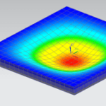
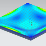
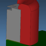
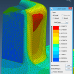
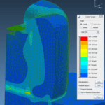
This analysis allows for the mechanical behaviour of the diaphragm and other structural components of the pressure sensor to be evaluated. When combined with stress analysis, it enables understanding of how mechanical stresses affect the deformation and strain distribution of the sensor.
Strain Analysis
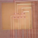
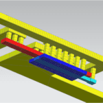
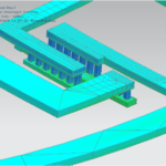
These simulations allow us to examine the strain distribution on the diaphragm and strain gauges. When combined with structural analysis, it is possible to determine how mechanical deformation affects the electrical properties of strain gauges.
Thermal Analysis
Such analyses allow for a better understanding of the impact of temperature variations on sensor performance by taking into account thermal impacts on both the mechanical and electrical properties of the sensor. The thermal expansion coefficient of materials, for example, can have an impact on strain distribution and electrical resistance in strain gauges.
Electrical Analysis
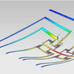
This analysis allows the evaluation of the strain gauges’ electrical response to applied pressure by taking into account the relationship between mechanical deformations/stresses and electrical resistance. Solving equations related to electrical conductivity, resistance changes, and the Wheatstone bridge configuration are part of the simulation.

Fluid-Structure Interaction (F.S.I.)
The analysis of the interaction between the diaphragm and the fluid (gas or liquid) to which the pressure sensor is exposed may necessitate simulating how pressure-induced diaphragm deformation affects the surrounding fluid and how fluid pressure influences diaphragm mechanical behaviour. The two-way coupling between our OOFELIE::Multiphysics Solver and Cadence’s flow solvers permits to conduct such F.S.I. simulations.
Dynamic Analysis
The evaluation of the sensor’s performance in dynamic or transient situations necessitates taking into account the time-dependent behaviour of both the mechanical and electrical features of the sensor, particularly in applications involving rapid pressure changes.
Material Properties Variation
The exploration of the impact of material property variations on sensor performance may need accounting for changes in material properties with temperature or other external conditions in simulations.
Optimization
Optimization of design parameters for increased sensor performance leads to simulations of various design configurations, materials, and dimensions to obtain the required sensor properties.
If you are interested in learning more about our pressure sensors simulation capabilities, please do not hesitate to contact us. We would love to hear from you and discuss how we can help you achieve your goals and solve your challenges.
